Before operating this unit, please read these instructions carefully, and save them for future use.
1. APP Download and Installation
Users can search “EseeCloud” on the APP store or “IP PRO” on Google Play or scan the QR code below to install the APP.
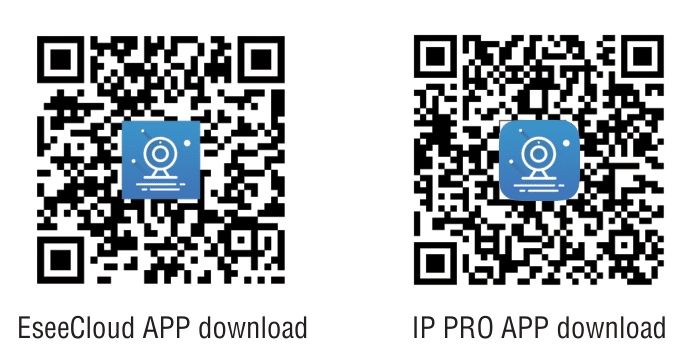
Note: For the IOS system, it requires the IOS 9.0 version or above.
For Android, Android 4.4 or above.
2. Software Operation
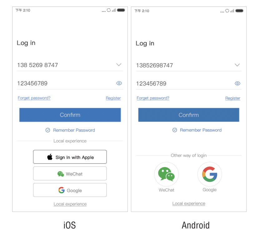
2.1. Log in
This APP supports “account log-in,” “third-party log-in,” and “local experience.”
Account log-in: At the log-in interface, input your user name/cellphone number/e-mailaddress and password, click “Confirm,” and log in.
Third-party log-in: Click the icon of the third-party network social software and authorize the app to log in.
Local experience: Users can use the app without logging in.
Remember the password: Supportremem-bearing the account and password that have been logged in, which is convenient for switching account login.
Note: Please pay attention that“Local experience” mode will be stored at local.
Once data is lost, it can’t be restored.
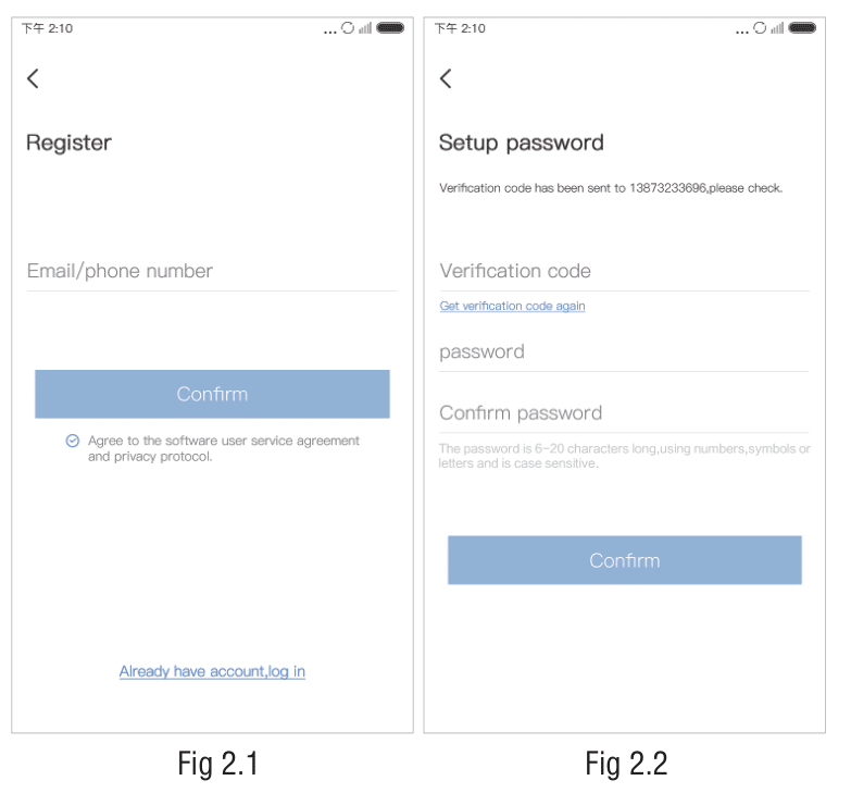
2.2. Registration
Input your cellphone number/email address to register and get a verification code.
Input the verification code and password, and click “Confirm.” After registration, it will move to the device list.
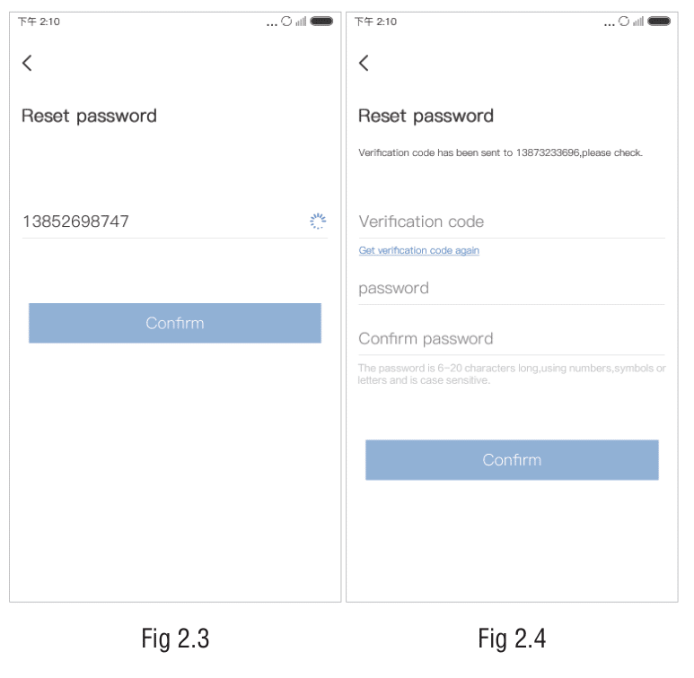
2.3. Reset Password
Input the registered cellphone number/email address to get the verification code.
Input the verification code, reset the password, and click “Confirm.”
Then, go back to the login interface and log in with a new password.
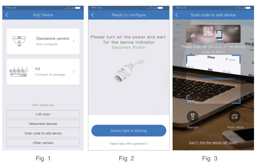
3. Add Device
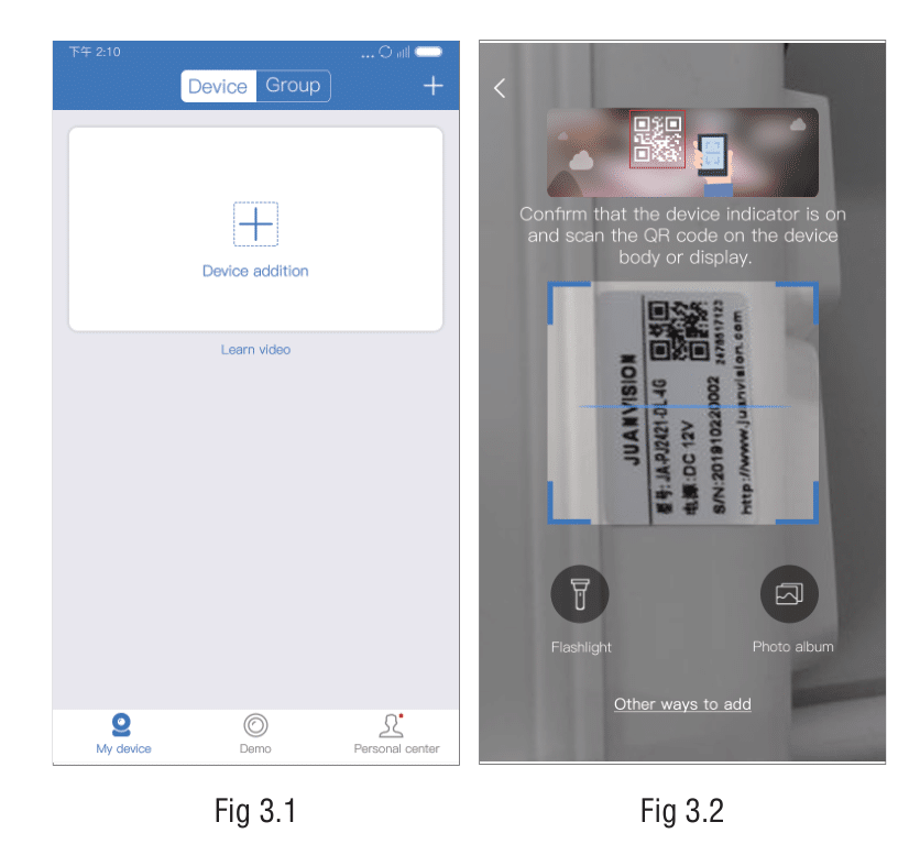
(1). After logging in, jump to the device list and click the “+” add button on the interface (Figure 3.1) to jump to the QR code scanning interface (Figure 3.2).
(2). If there is a QR code on the device or on the monitor, please refer to the QR code scanning process of adding the device in 3.1. If you cannot find the QR code, please check the adding process in 3.2.
Note: When adding the device, please make sure that the phone camera, WIF, and positioning permission are turned on.
3.1. Scanning and adding devices (There is a QR code )
How to add a non-networked device
(1). Please go to the mobile phone system settings and select the device hotspot starting with IPC. The default password is 11111111 (Figure 3.3)(Notice: please keep connected with the device hotspot);
(2). Open the EseeCloud app, input the QR code scanning interface to scan the device QR code (Figure 3.4), and on the search device interface(Figure 3.5), click “Add”;
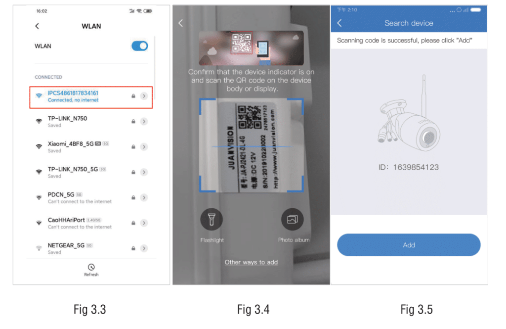
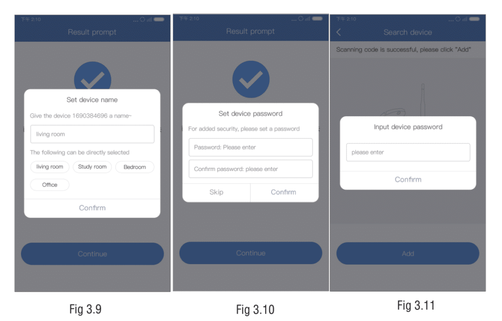
(3). For viewing and using via WiFi or other networks, please choose to use it remotely; if there is no network, connect the camera at close range for viewing, and please select a local connection (Figure 3.6). Remote view: Click the “Remote view ” button (Figure 3.6) to go to the configuration network interface. The system will display the WiFi search for the device below the interface. Select or enter the router’s WiFi name and password at home (Figure 3.7), and click OK to configure the device WiFi(Figure3.8); after the configuration is successful, follow the interface to complete the device name and password settings (Figures 3.9 and 3.10), and return to the device list after adding successfully.
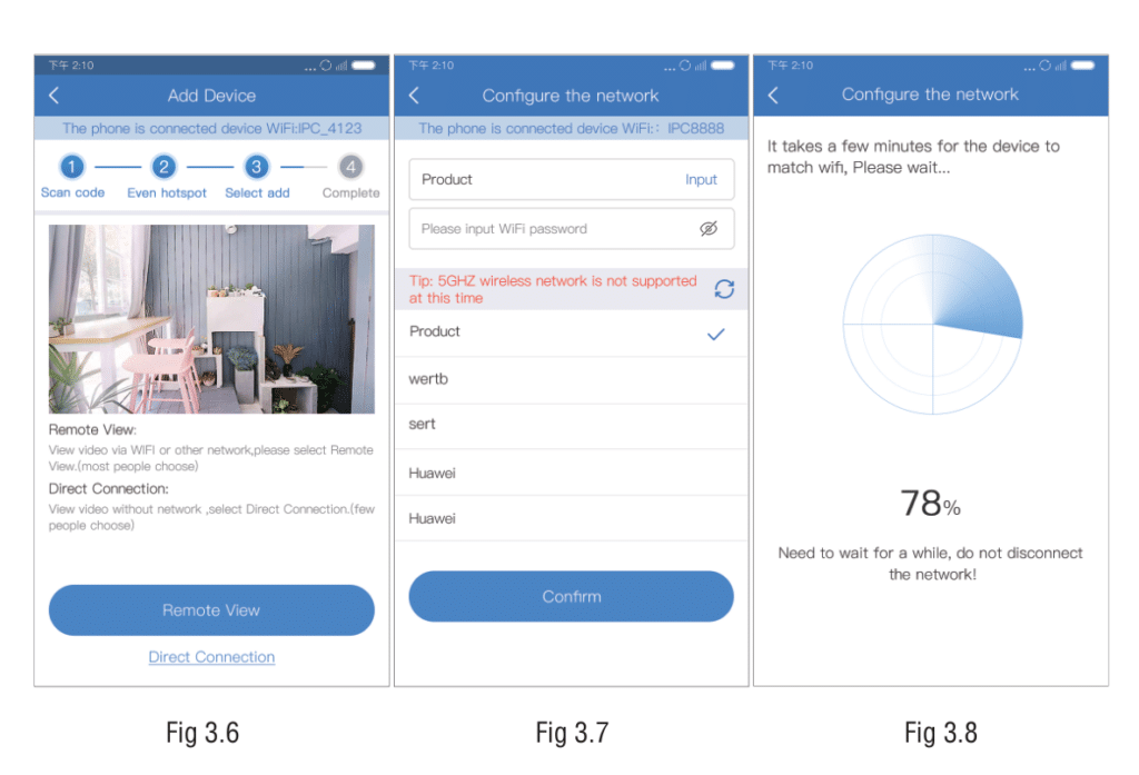
Direct connection: Click the “Direct connection” button (Figure 3.6) and pop-up box for setting the device name, and follow the interface steps to complete the device name and password settings (Figure 3.9, 3.10); after adding successfully, return to the device list to display the added device.
How to add networked devices
(1). Open the EseeCloud APP, enter the QR code scanning interface to scan the QR code on the device or the monitor (Figure 3.4), and in the search device interface (Figure 3.5), click “Add”;
(2). Follow the interface to set the device name (Figure 3.9), input the correct device password (Figure 3.11) (skip this step if the device has no password), and return to the device list after adding successfully.
3.2. Other adding methods (Device QR code cannot be found)
How to add a non-networked device-standalone camera
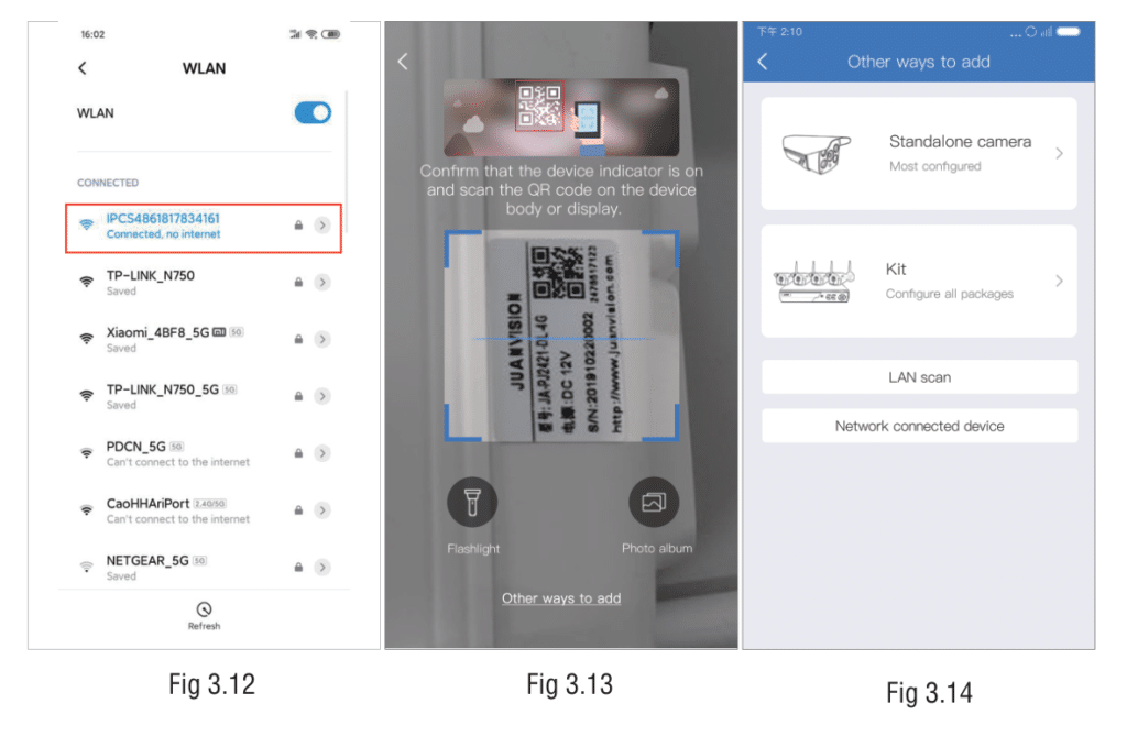
(1). Please go to the phone system settings and select the device hotspot starting with IPC. The default password is 11111111 (Figure 3.12) (please keep connected with the device hotspot during the connection process);
(2). Open the EseeCloud App, enter the QR code scanning interface, and click ” Other Ways to Add ” (Figure 3.13);
(3). Select the wireless standalone camera (Figure 3.14). For the subsequent network configuration steps, please refer to the adding process in 3.1 Adding a non-networked device(3).
How to add networked devices
1: Process of adding wireless NVR Kit
(1). Please connect the KIT device to a router that can access the Internet through a network cable;
(2). Open the EseeCloud App, input the QR code scanning interface, and click ” Other Ways to Add ” (Figure 3.13);
(3). Select the KIT(Figure 3.14);
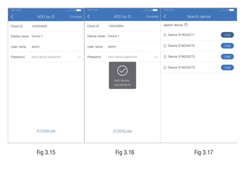
(4). After inputting the device ID, name, and device password (Figure 3.15),
click complete in the upper right corner to return to the device list after the addition is successful (Figure 3.16).
2: Adding process of LAN search device
(1). Please go to the mobile phone system to set the currently connected
WiFi of the connected device, and ensure that the mobile phone and the
the device is under the same routing WiFi;
(2). Open the EseeCloud APP, enter the QR code scanning interface, and
click “Other Ways to Add” (Figure 3.14);
(3). Select LAN scan (Figure 3.15).
(4). Select the required device ID in the scanning interface (Figure 3.17), click Add to enter the ID-adding interface, enter the device name and device password, and click Complete in the upper right corner to return to the device list after the addition is successful.
3: Process of adding networked devices
(1). Open the EseeCloud APP, enter the QR code scanning interface, and click
”Other ways to add” (Figure 3.13).
(2). Select the networked device(Figure 3.14);
(3). After entering the device ID, name, and device password (Figure 3.15),
click complete in the upper right corner to return to the device list after the addition is successful (Figure 3.16).
3.3. Add Shared Device
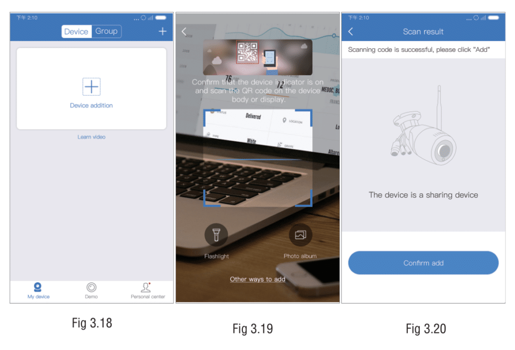
Click the “+” add button on the device list to jump to the scan code scanning interface, scan the shared device QR code, enter the search device interface, confirm the addition, and return to the device list interface to prompt the addition result. (Figure 3.18-3.20).
4. Preview Playback
4.1. Operating instructions
Device list: After adding the device successfully, the device list will display the device card, showing the device name, online and offline status, sharing, playback, alarm messages, settings, and more function buttons; click the thumbnail to enter the preview interface. (figure 4.1).
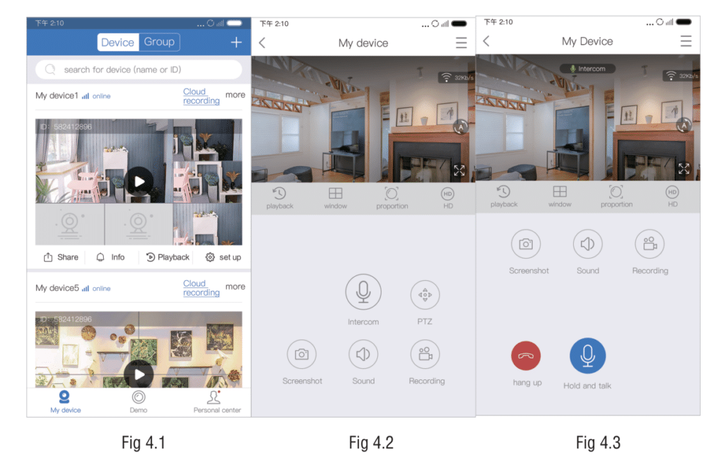
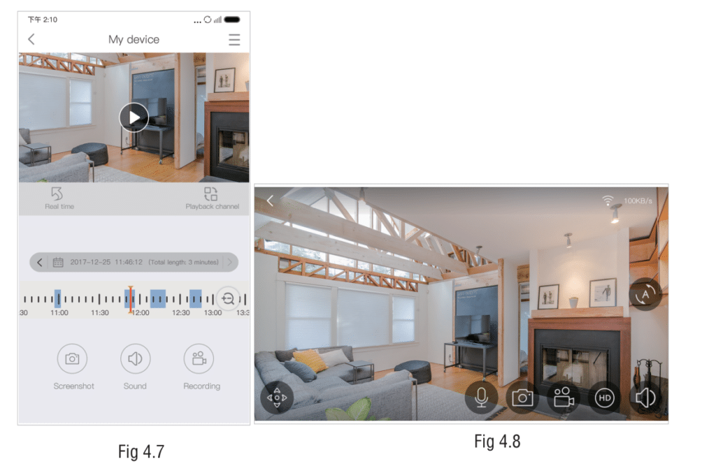
Preview: Click the thumbnail of the device channel to enter the preview interface, and click the full-screen button to switch to landscape display (Figure 4.7).
The preview interface functions can be adapted according to the device.
Intercom function: Click the intercom button (Figure 4.2), and the APP initiates an intercom to the device. After the launch is successful, it prompts that the intercom is successful. The interface displays the intercom and hang-up buttons (Figure 4.3). Click the hang-up button to end the intercom (when the device is in the intercom state, other users cannot initiate an intercom to the device).
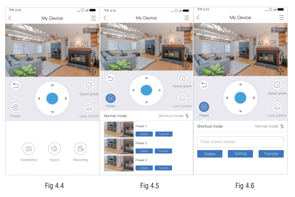
PTZ preset function: Click the PTZ button (Figure 4.2) to display the PTZ function (Figure 4.4). You can slide the control button or click the direction arrow to control the camera direction and adjust the monitoring area.
(1) Click the preset button to display the preset position below the interface(Figure 4.5), you can add, recall, and delete preset positions; preset positions are divided into normal mode (Figure 4.5) and shortcut mode (Figure 4.6);
(2) Click the speed level button to pop up the PTZ speed level selection pop-up box; click the lens control button to change the camera focal length, magnification, and other functional parameters.
Playback: Click the playback button (Figure 4.2) to switch to the playback interface (Figure 4.7); you can view the video and filter the recording date.
4.2 Icon function description
| Icon | Functions | Details |
  | Switch definition | Switch the definition of previewing. |
  | Audio | Select whether to play the sound of the area where it is captured by the device. |
 | Cruise | When the single screen fails to fully display the monitor screen after opening, set cruise left and right |
  | Installation mode | Select the installation mode of the device: upside-down mode and wall-mounted mode. |
 | Fisheye mode | Applicable to the upside-down installation mode and the wall mount installation mode. After the selection, the preview screen of the device is converted to the fisheye mode. |
 | Cylindrical mode | Applicable to the upside-down installation mode, the preview screen of the device is switched to the cylinder mode after selection. |
 | Corridor mode | Applicable to the upside-down installation mode, after selecting the device’s preview screen to convert to corridor mode. |
 | Quad screen mode | Applicable to the upside-down installation mode, after selecting the device’s preview screen to convert to quad screen mode. |
 | Expand mode | Applicable to the wall mount mode, the preview screen of the device is switched to the expanded mode after selection. |
 | Asteroid mode | Applicable to P720 devices, the preview image of the device is converted to asteroid mode after selection. |
 | Crystal Ball Mode | Applicable to P720 devices, the preview screen of the device is converted to crystal ball mode after selection. |
 | Expand mode | Applicable to P720 devices, the preview screen of the device is switched to the expanded mode after selection. |
 | VR mode | When applied to landscape, some devices can use VR mode. After selecting, the preview screen of the device is converted to VR mode. |
  | Full screen/exit full screen | Suitable for horizontal screen and vertical screen switching. The full-screen icon is on the left, and the full-screen icon is on the right. |
 | Light control | Dual light source: control device video color mode, including infrared, full color, and smart mode. Light bulb device: The switch of the light bulb that controls the device, including four items turning on, off, smart, and automatic. |
 | Screenshot | Capture the device preview screen seen on the current phone screen. |
 | Recording | Take a preview of the device you see on the current phone screen. |
 | Audio | Suitable for devices with microphone hardware. |
 | PTZ button | Available when it is PTZ camera, click to PTZ control windows. |
  | Switch playback/live. | Switch video playback and play in real-time. |
 | Date Selection | Playback date selection |
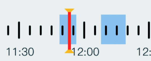 | Playback timeline | Drag the timeline to modify the playback time, and click the calendar button to switch the date. The blue area on the timeline indicates the time period during which the video was recorded. |
 | Screen width-to-height ratio | In addition to the panoramic device, when previewing the playback interface, the video screen aspect ratio can be set to support three different ratio selections. |
 | Timeline zoom button | The zoom & focus of the playback timeline can be adjusted. |
4.3 Gesture operation illustration
1) Two-finger touch screens are stretched out to enlarge the picture.
2) Two-finger touch screens are stretched inward to reduce the picture.
3) Double-click on the screen to zoom in and out.
4) Single-point left/right and up/down to slide the screen.
5. Data recharge of 4G camera
5.1 4G Card Device Management and Recharge
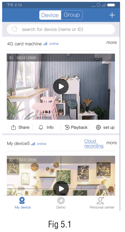
4G camera management:
(1) When the flow is sufficient, the device list is displayed normally (Figure 5.1), and when the flow reaches the warning value, the current remaining flow is displayed (Figure 5.2);
(2) Click on the 4G card management (Figure 5.3) or flow warning value prompt text in the settings to jump to the 4G card management interface(Figure 5.4), and you can view the information about the 4G card traffic usage, signal level, etc.
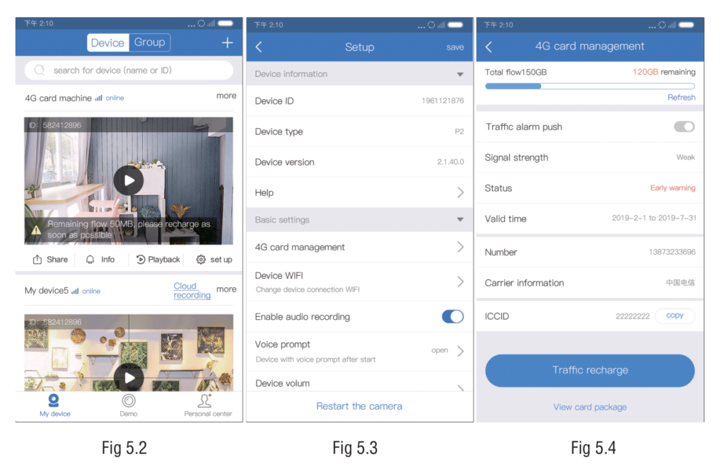
4G card data recharge process:
(1) On the 4G card management interface, click the “Recharge Data” button(Figure 5.4) to enter the data purchase interface (Figure 5.5). After selecting the package and payment method, click Pay Now (Figure 5.6);(2) After completing the payment, return to the APP and display the details of the result. After the recharge is successful, the recharge device, traffic, and other information will be displayed (Figure 5.7).
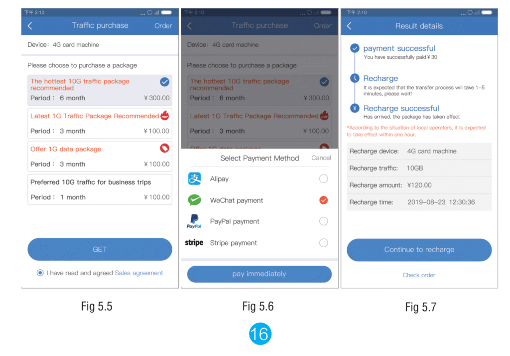
Note: The effective time of the recharge depends on the local operators and is expected to take effect within one hour.
5.2 4G Camera Abnormal Conditions
4G camera device list abnormal situations:
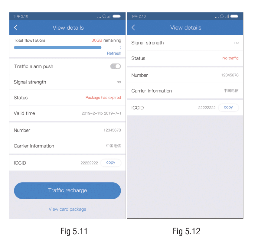
When the 4G camera has no traffic, and the package expires, the device list displays the corresponding status (Figures 5.8 and 5.9). Click View Details to enter the 4G card details interface and display the corresponding status based on the offline reason of the device list (Figures 5.10 and 5.11), Click on Data Recharge to enter the 4G card data recharge process.
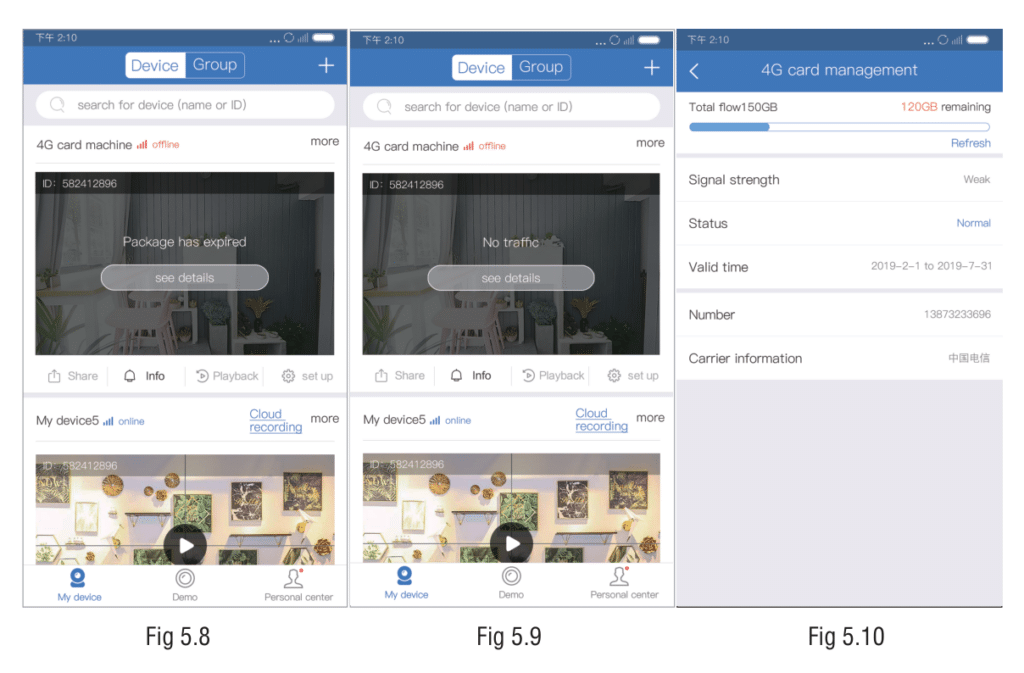
Note: When the camera is plugged into a non-equipment 4G card, it will not support data package recharge, traffic query early warning, and other functions (Figure 5.12).
6. Setup Instructions
Note: The function in the list will be displayed only if the camera hardware supports it. If the camera does not support a function in the list, the APP will hide the function setting item.
6.1. Stand-alone device setup
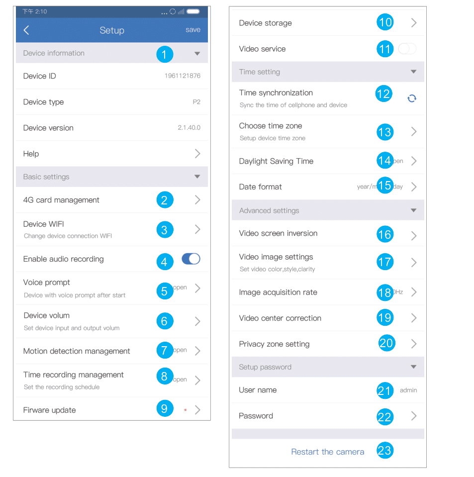
| NO. | Functions | Details |
| 1 | Device info | View device ID, device type, device version, usage help |
| 2 | Video sound | Control device audio switch |
| 3 | Beep | Device prompt tone switch can set the prompt tone language |
| 4 | Device volume | Set the input and output volume of the device |
| 5 | Motion detection management | Can set human shape detection switch, detection recording, alarm switch status, set detection area, support custom alarm voice, and sensitivity selection |
| 6 | Time recording management | Control the recording switch and set the recording schedule(time period for automatic recording) |
| 7 | Firmware update | Device firmware online update |
| 8 | Device Storage | TF card status, available capacity, forma |
| 9 | Video service switch | Control the device’s switch of preview permission |
| 10 | 4G SIM card management | Check fee of 4G SIM card mobile data plans, and 4G SIM card operators, Wi-Fi signal, mobile data flow |
| 11 | Synchronised time | Sync device and phone time |
| 12 | Select time zone | Set the time zone for your device |
| 13 | Summertime | Enable summer time |
| 14 | Date format | The date display format can be selected, including the date/month/year, year/month/date, month/date/year |
| 15 | Video screen inversion | Support panoramic device on video screen up and down,left and right reverse setting |
| 16 | Video image settings | Set sharpness, mode, and image style |
| 17 | Image acquisition rate | Set the acquisition frequency of the device |
| 18 | Video center correction | Video area size can be set |
| 19 | Privacy zone setting | Set the privacy zone in the preview interface, will cover the video in the area as a color block |
| 20 | User name | Device User name |
| 21 | Password | Device password |
| 22 | Device WiFi | Can change network configuration of the device |
| 23 | Restart the camera | Can restart the camera |
6.2. Mini NVR setup
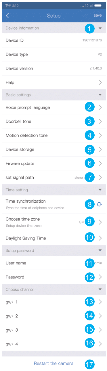
| NO. | Functions | Details |
| 1 | Device information | Display device ID number, device type, device version, and use help entry |
| 2 | Voice Prompt language | Select device prompt tone language |
| 3 | Doorbell tone | Set the alarm tone of the doorbell device |
| 4 | Motion detection tone | Set motion detection alarm tone to support custom alarm sound |
| 5 | Device storage | Display device TF card status |
| 6 | Firmware update | Update the firmware version of the mini NVR device and the cameras connected to all channels on the device |
| 7 | Set WiFi channel | Device channel setting |
| 8 | Time synch- ronization | Sync device and phone time |
| 9 | Select time zone | Set the time zone directly for your device |
| 10 | Summer time | Enable Summer time |
| 11 | User name | Set user name |
| 12 | Password | Set password |
| 13 | Channel 1 | Enter the setting interface of the mini NVR channel 1 device |
| 14 | Channel 2 | Enter the setting interface of the mini NVR channel 2 device |
| 15 | Channel 3 | Enter the setting interface of the mini NVR channel 3 device |
| 16 | Channel 4 | Enter the setting interface of the mini NVR channel 4 device |
| 17 | Reboot the device | Restart the mini NVR device |
6.3. Mini NVR channel setup
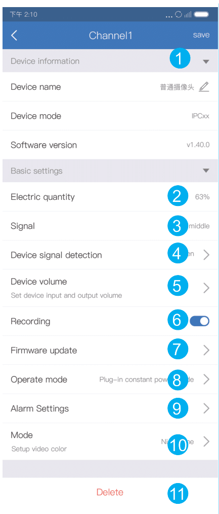
| NO. | Functions | Details |
| 1 | Device information | Device name, device mode, firmware version |
| 2 | Power status | Battery device shows device power status |
| 3 | Signal | Display the current signal strength of the device, divided into high, medium and low |
| 4 | Device signal detection | Detecting device signal strength |
| 5 | Device volume | Set the volume of device input and output |
| 6 | Recording switch | Motion detection recording switch |
| 7 | Firmware update | Update device firmware |
| 8 | Operate mode | Battery device-specific settings, whether the device is in plug-in or low-power mode |
| 9 | Alarm settings | Set alarm time period and recording time after alarm, select alarm time period, alarm message push switch, detection sensitivity adjustment |
| 10 | Mode | Support for setting video color |
| 11 | Delete | Delete the device on this channel on the mini NVR |
6.4. APP personal center setup
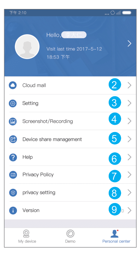
| NO. | Functions | Details |
| 1 | Personal information | Account, name, email address, password change, logout function |
| 2 | Cloud mall | Cloud storage mall entrance, click to enter the purchase interface of cloud storage service |
| 3 | Setting | Manage shared devices to delete users shared by receiving devices |
| 4 | Screenshot/ Recording | Traffic reminder switch, traffic statistics, shake to add, upload crash log |
| 5 | device share management | Save screenshots and videos in the preview interface |
| 6 | Help | Add device help, preview and playback help, FAQs |
| 7 | Privacy policy | View APP privacy policy and user agreement |
| 8 | Privacy setting | You can view all the phone permissions required by the APP, and support the permission to turn on or off |
| 9 | Version | The current version, the new version reminder |